Fall ’18 Semester Summary

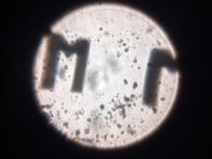
This semester, we collected 90 datasets of low resolution flatworm images to train the neural network on. The tomographic output is a high resolution and has a wide field of view. When training on the neural net is complete, we will be capable of single-shot reconstruction. Assuming the training is successful, we will write a paper on this research during the spring semester.

The foldscope project is proceeding more rapidly now that the flatworm project is nearing completion. We have prototyped multiple FPM-compatible assemblies using Legos and other material. Once our design is finalized, instructions for duplication will be posted to the blog along with images of the final product. We have experimented with apache cordova and other tools that will allow us to wirelessly control our LED array in sync with an iPhone camera using a simple app. The  ESP8266 dev board will be the key to wireless synchronization. The FPM app and any other software will be made available once complete so that any person with a foldscope, LED array, and cell phone can achieve single-shot Fourier reconstruction.

Deep Learning for Optimization of Fourier Ptychography

Our foldscope research is an extension of research completed this summer and during the 17/18 school year in Professor Ganapati’s lab. Using a neural network trained on low resolution input data and corresponding high resolution FPM reconstructions, we simultaneously optimize the illumination pattern and reconstruction algorithm.

The neural network identifies a single LED pattern to encode as much information about the sample as possible into one low resolution input image. By restricting our samples to a fixed type, we are able to significantly reduce the information requirements for reconstruction, making single-image reconstruction possible. The optimized reconstruction is also non-iterative, further improving temporal resolution.

For any given sample type, after training, we are able to generate a high resolution reconstruction from a single low resolution input image. We now aim to apply this technique with the foldscope to create an extremely low cost microscope capable of single image super-resolution microscopy.

Preprints:

“Optimal Physical Preprocessing for Example-Based Super-Resolution

Illumination Pattern Design with Deep Learning for Single-Shot Fourier Ptychographic Microscopy

Introduction to the Foldscope

The foldscope is a paper microscope project designed to make quality microscopy portable and affordable. The bulk of the microscope is an origami-style paper assembly with sliders for manipulating the x, y, and z axes. The small lens can be affixed to a cellphone camera for easy imaging.

Foldscopes are useful anywhere lightweight, durable, and inexpensive scientific equipment is sought. They are used with paper centrifuges for low cost malaria detection, and in homes and schools to excite an interest in science on a budget.

Our Foldscopes were easy to assemble with the provided instructions. We magnified a microscope slide and took a cell phone camera image while holding the slide up to a light.

The slide and lens were both somewhat dusty, and we could possibly have improved the focus with more careful adjustment. We decided, however, that this image would suffice as a proof of concept. Later, we built a temporary stand from Legos. The added stability improved overall image quality.

More information is available on the Foldscope website

And YouTube:

Manu Prakash: A 50-cent microscope that folds like origami

How to save 51 billion lives for 68 cents with simple Engineering


Notes from “Multiplexed coded illumination for Fourier Ptychography with an LED array microscope” by Tian et al.

This paper forwards the work of Zheng et al. by improving the temporal resolution of FPM.

FPM depends on many different angles of illumination to encode different Fourier space information into each low resolution image. The multiplexing technique posits that an image with multiple illuminating LEDs is equivalent to the sum of images under each component illumination, provided the LEDs are a sufficient distance apart. Instead of using M images, we can use one image illuminated by the same M LEDs. This reduces the exposure time of each image by M and decreases the overall size of the low resolution dataset.

Tian et al. successfully implemented their multiplexed data collection strategy. By reducing the size of the low resolution dataset, they speed up data collection and use less memory on data storage. They also reduce data collection time by reducing exposure during imaging, as using many LEDs increases the overall brightness of each image.

This technique offers a marked improvement over standard Fourier Ptychography but still depends on the collection of many low resolution input images and a fairly slow iterative reconstruction algorithm. Even with multiplexing, FPM is significantly slower than traditional single-shot microscopy.

Notes from “Wide-field, high-resolution Fourier ptychographic microscopy” by Zheng et al.

Fourier Ptychographic Microscopy is a super-resolution imaging technique. It uses many low resolution images of an object to generate a single high resolution composite.

A microscope’s space-bandwidth product describes the relationship between resolution and field of view. A good space-bandwidth product allows the microscope to simultaneously display detail and context — a valuable quality in biomedical and other microscopy. Space-bandwidth product is expensive and difficult, sometimes impossible, to enhance through physical alterations to the magnifying lens. Instead, computational techniques like Fourier Ptychography enhance resolution in post-processing.

Fourier ptychographic microscopy (FPM) is implemented by replacing the light source of a standard bright field microscope with an LED array. Single LEDs are sequentially illuminated. One low resolution image of the sample is collected for each LED. After all of the images are collected, the FPM reconstruction algorithm iteratively combines the Fourier space of the low resolution image stack. The result is a high resolution image that retains the wide field of view of the low resolution stack.

The greatest drawback of FPM is its time-intensiveness. Creating the low resolution image stack requires collection of dozens of images, which can be impractical. To enhance the usefulness of Fourier Ptychography, the data collection phase must be made faster.


Using the ESP8266 NodeMCU Board

The wifi ESP8266 development boards that we ordered came in. Took me a solid day of trouble shooting to finally get to the point where my MacBook Pro would recognize the existence of the ESP8266 being plugged into its USB port. The arduino IDE would not recognize the ESP board in the sketch—> ports section. Selecting the correct port is necessary to upload a sketch to the board so I scoured online forums and found that a USB to UART driver needs to be installed in order for the connection to be made. After installing and reinstalling to no avail, I eventually changed the board  sketch–>board to some other board and then back to the ESP8266 and finally the IDE recognized the board. The next problem that came up was that I was getting compiling errors that were board specific. The code was syntactically correct so there was obviously some board connection issues still.

I found some other mac users online that were having the same problem. I think it had something to do with the USB-UART drivers being “signed” and the computer needing authorization to use them. I tried running a few suggested terminal commands which fixed the problem. Currently I have the blink.ino sketch running on the ESP8266 to confirm that I can successfully upload sketches to the board.

I’ve been looking at the code and immediately noticed a potential problem for using this board: all the code I’ve found so far has been written to be used in home wifi systems where there is a single SSID and password to get onto the network. At Swarthmore there is Eduroam which, requires a swarthmore account to gain access. We all have these accounts but figuring out how to code our user credentials for the ESP8266 board to get access to the internet might be a bit of a challenge.

I will be taking one of the boards home with me and I will get it working on my home network which will be a less complex process.  We will have to solve the Eduroam network access problem once the spring term starts up again.

Progress

This week Megan and I discussed our options with regards to establishing wireless communication between a mobile phone and the Arduino. For the past week or so I was operating under the assumption that the Wifi module we were given (ESP8266) would solve all our problems and that it would be a simple initialization process and we could have at least a simple web server hosted on it. The ESP8266 runs off of 3.3V and thus requires 3.3V logic from our microcontroller. As we are using a 5V Arduino Leonardo we would need a 3.3V to 5V logical level shifter. The module additionally is not breadboard friendly because of its pin grouping configuration. There was also confusion about how to use it after coming across conflicting information about the board.

After doing some research, we learned that it is actually quite typical to use the ESP2866 via a development board with the module embedded. Many of the resources we found used the ESP8266 NodeMCU development board which can be programmed in the Arduino language in the Arduino IDE. Considering that the only input the board would be receiving is through the internet through the wifi module embedded into the dev board, and the only output would be the single digital signal pin for the LED matrix, we decided that the NodeMCU board could be used as the single microcontroller for the project. 

The ESP2866 NodeMCU board would simplify and condense the scale of the wiring. One drawback however is that the board is a 3.3V logic device and the LED matrix we are using requires a 5V digital control signal. This is a minor inconvenience but easily remedied with a  logic level shifter purchased through Adafruit (SN74AHCT125N) link: https://www.adafruit.com/product/1787


Getting to Know the ESP8266 Wifi Module

  • 3.3V device so to use with an Arduino Uno we will need a 5V to 3.3V Logic level converter.
  • Module also draws more current than the 3.3 V pin on the uno so a voltage regulator might be necessary or use another power supply that is rated or up to 500 mA.
  • Might be simpler to buy a dev board with the ESP8266 chip onboard and program the board directly with arduino code.

The HUZZAH breakout board from Adafruit Industries looks like a good bet for our initial set Foldscope optimization setup.

  • The Adafruit Huzzah Board has a built in 500 mA rated 3.3V regulator, is breadboard friendly and has plenty of documentation from Adafruit. It is also inexpensive.

Questions:

  • What exactly is FTDI cable and uploading? Why is it more desirable over uploading via USB?