Debugging The LED Array

Note: This post was intended to be published in early March 2020, but was delayed by the COVID-19 pandemic.

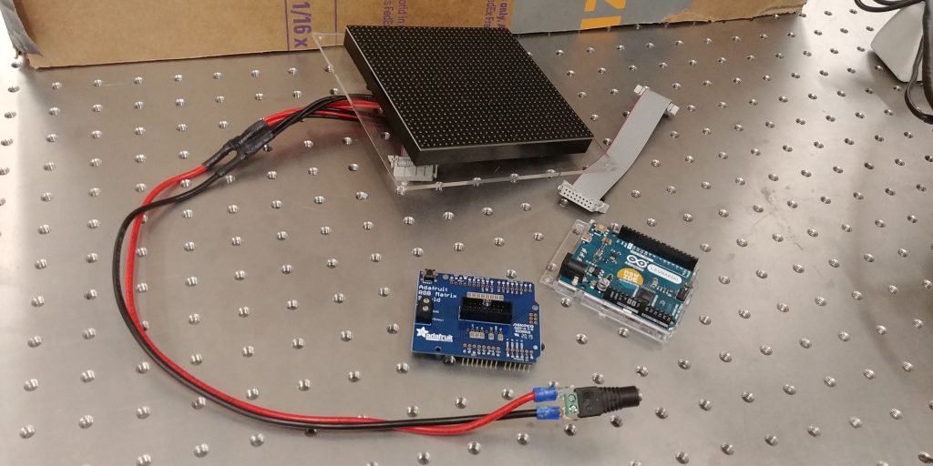
After connecting the Arduino to the LED array — via the RGB Matrix Shield — we tried to run some basic color and shape tests to ensure that everything was running smoothly. Unfortunately, we had an issue where only half of the LED array was illuminated properly.
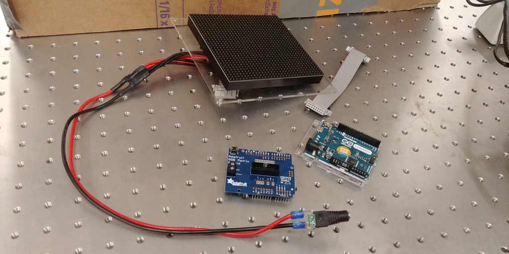
Pictured, the three components in the LED array

Thus, I began an extensive debugging process. When the 32×32 LED Matrix was receiving power and no data the entire matrix was illuminated (pictured below).
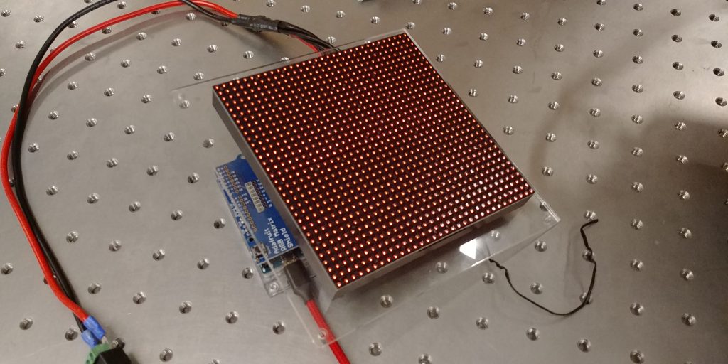
Pictured, the LED array powered but with no data.

As a result, I suspected that the issue was data related. With either the ribbon cable or the LED Matrix at fault. As such, I unmounted the array and swapped out the ribbon cable. This didn’t solve the issue.

Thankfully, we had another 32×32 LED Matrix in the lab so I mounted the other LED Matrix with the new ribbon cable. This, too, didn’t solve the issue.

Just to be safe, I again swapped the new ribbon cable for the previous ribbon cable. Again, no change.

Having ruled out both the ribbon cable and the LED Matrix itself as issues, I circled back and did a quick sanity check to make sure there wasn’t a flaw in the code that I was running. This was the same code that was run in the summer of 2018 so I assumed it was good, but it never hurts to check. I ran some example code straight from the documentation. This too failed to solve the problem.

Thinking it may be a power issue, I reseated all the power connections in the entire LED Matrix +Arduino setup and then grabbed the multimeter to check that the correct amount of power is being delivered to the matrix. The multimeter confirmed that there was power delivery to the LED Matrix and to the Arduino. I then checked the power supply to make sure that it was rated to deliver the correct amount of amps and volts (it was). Lastly, I used the multimeter to check if the LED Matrix was actually receiving the 5V and 2A it was supposed to be. Pictured below is part of that process.
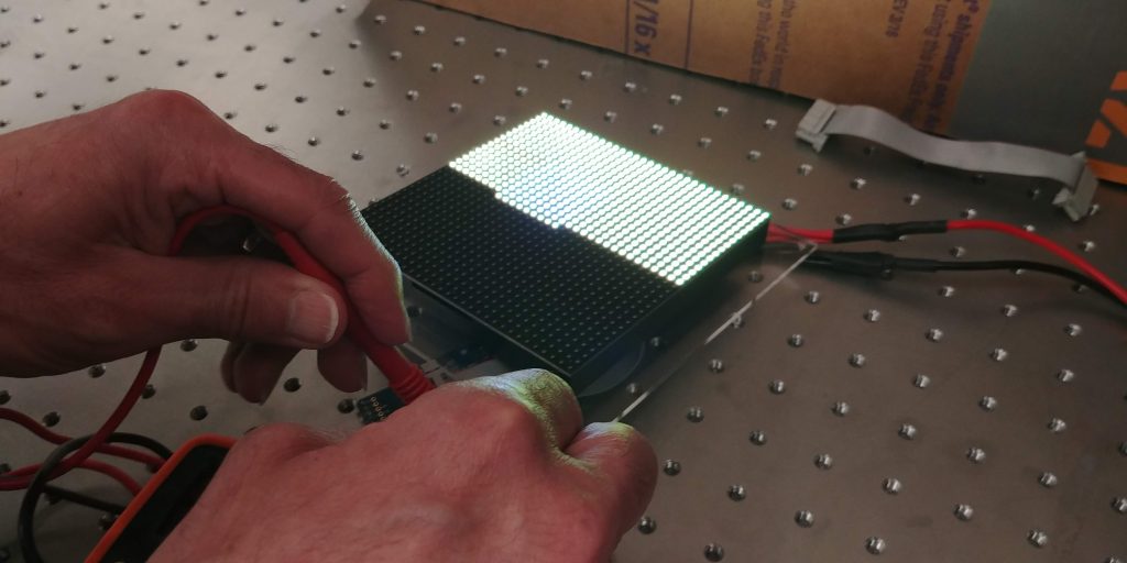
Pictured, probing the LED array with a multimeter

Frustratingly, the multimeter proved that the LED matrix was receiving 5V and 2A.

Thinking it may be a soldering issue, I brought in our resident electronics specialist, Ed, to look at our soldering work. He confirmed that it looked fine. He also went over my power work and came to the same conclusions that I did. 

At this point, both he and I were pretty stumped.  I don’t think it’s an Arduino issue because the Arduino boots fine. It could be an internal issue with the shield and, if so, I’d need to wire the ribbon cable to the Arduino via jumper wires to double-check. Ed thinks it might be a power issue, but I am skeptical since everything on the multimeter makes sense. 

I planned to go back into the lab and follow up on my hunch, but then Swarthmore College switched to online learning due to the COVID-19 pandemic and I was/am unable to get into the lab to debug any further.

Setting Up The RGB Matrix Shield

Note: This post was intended to be published in mid-February 2020, but was delayed by the COVID-19 pandemic.

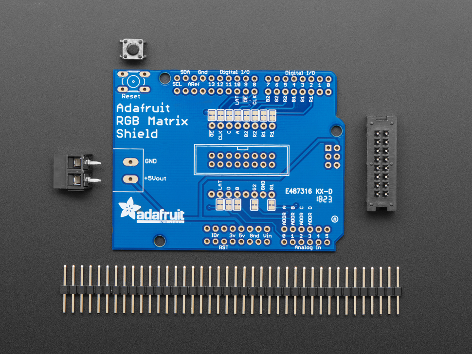
The RGB Matrix Shield has arrived! Like many products from Adafruit, some assembly is required to get the shield up and running.

Pictured, all of the components included when purchasing the RGB Matrix Shield Shield. Picture from the Adafruit Website

Unfortunately, none of the current Ganapati lab members had soldered in over a year. So, after a quick refresher, we set about soldering together the RGB Matrix Shield. The first step was to solder on the reset switch, the screw terminals, and the male ribbon connector.

Pictured, the components successfully soldered on the RGB Matrix Shield

The silkscreen made it very easy for us to ensure that we didn’t solder on any component backward. For example, the notch on the ribbon connector silk screen lined up with the notch on the ribbon connector part. This may seem trivial, but any design choice to lower the chance of failure is much appreciated.

After soldering on the components, the next thing we did was solder on all the header pins. This proved to be slightly annoying because we wanted to ensure that the header pins were orthogonal to the shield PCB in order to eliminate any problems down the road. This was not as easy as we’d hoped it would be.

After some adjustments to our soldering approach, we managed to get all the header pins oriented in an acceptable fashion and completed the shield assembly. Up next, putting all the pieces together.

Pictured, 32×32 LED Matrix, RG Matrix Shield, and an Arduino Leonardo

Back To Basics, New and Improved

Note: This post was intended to be published in early February 2020, but was delayed by the COVID-19 pandemic.

At the end of the 2019 Fall semester, I got the dome array set up and working for a short while. Unfortunately, over the winter months, the teensy Arduino managed to break on this dome as well. As such, we decided to “go back to basics” and reimplement the original 32×32 LED matrix because it didn’t have nearly as many technical hiccups.

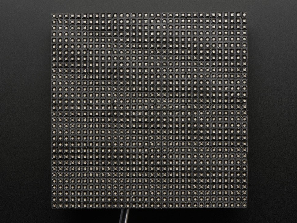
Pictured, a 32×32 LED Matrix. Photo from Adafruit’s Website.

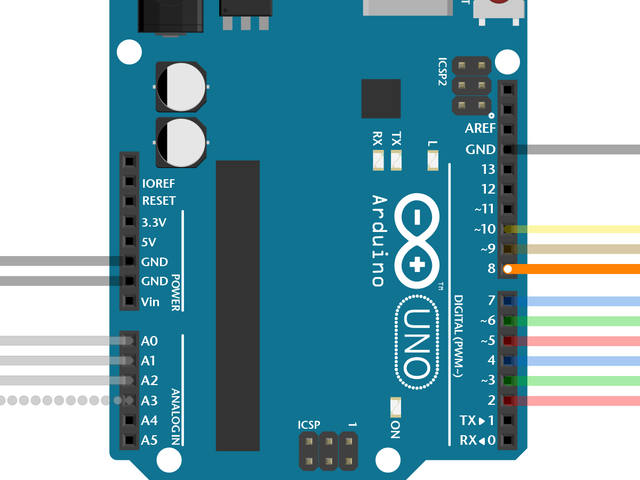
In the old setup we wired the Arduino directly to the ribbon cable that was connected to the LED array via jumper wires and a breadboard, but — as you can see below — this wiring is a quite involved process.

Pictured, Final Amount Of Jumper Cables Connected To A Ribbon Cable In Order To Interface With An Arduino
Pictured, Final Amount Of Jumper Cables Connected To An Arduino In Order To Interface With A Ribbon Cable

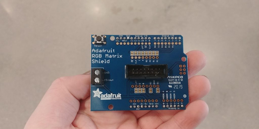
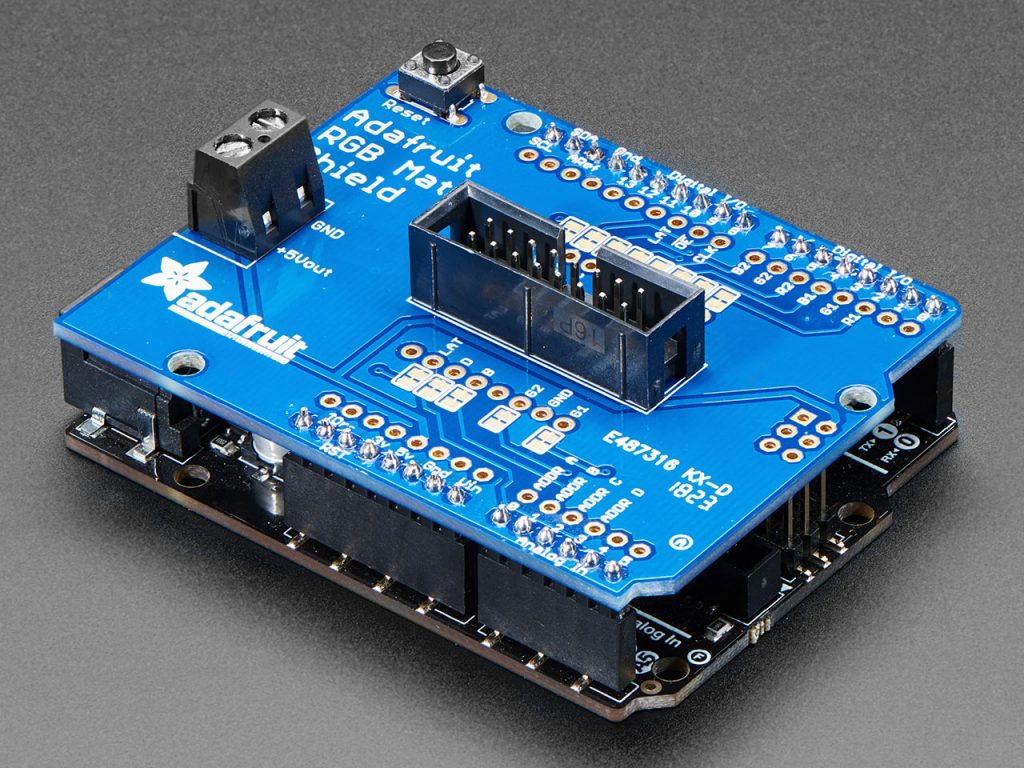
With a little bit of poking around, I found out that Adafruit sells an RGB Matrix Shield. In fact, they recommend using this shield to connect from an Arduino to a ribbon cable. With this shield, all you need to do is plug in the ribbon cable. Much simpler and less error-prone than working with ~35 jumper wires.

RGB Matrix Shield. Photo from Adafruit’s Website

As such, the lab has decided to buy one to connect our arduino to the LED matrix. It is currently enroute as I write this post!