Note: This post was intended to be published in mid-February 2020, but was delayed by the COVID-19 pandemic.
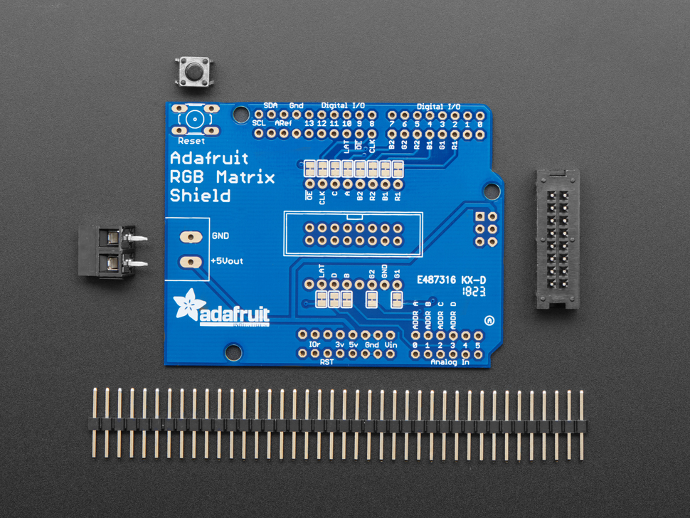
The RGB Matrix Shield has arrived! Like many products from Adafruit, some assembly is required to get the shield up and running.
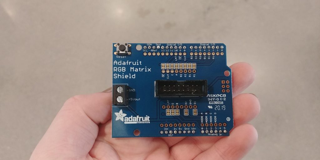
Unfortunately, none of the current Ganapati lab members had soldered in over a year. So, after a quick refresher, we set about soldering together the RGB Matrix Shield. The first step was to solder on the reset switch, the screw terminals, and the male ribbon connector.
The silkscreen made it very easy for us to ensure that we didn’t solder on any component backward. For example, the notch on the ribbon connector silk screen lined up with the notch on the ribbon connector part. This may seem trivial, but any design choice to lower the chance of failure is much appreciated.
After soldering on the components, the next thing we did was solder on all the header pins. This proved to be slightly annoying because we wanted to ensure that the header pins were orthogonal to the shield PCB in order to eliminate any problems down the road. This was not as easy as we’d hoped it would be.
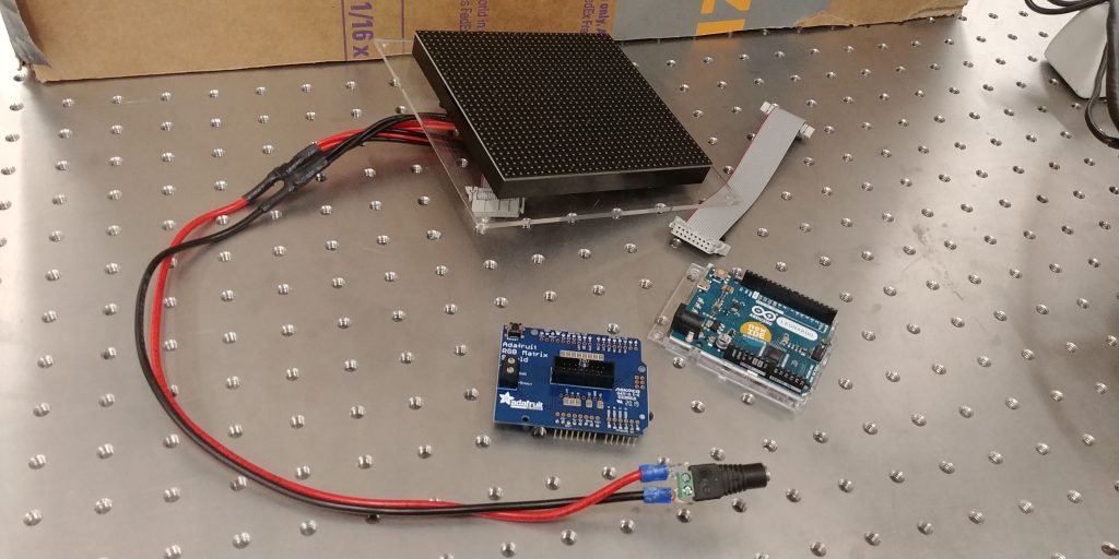
After some adjustments to our soldering approach, we managed to get all the header pins oriented in an acceptable fashion and completed the shield assembly. Up next, putting all the pieces together.