Debugging The LED Array

Note: This post was intended to be published in early March 2020, but was delayed by the COVID-19 pandemic.

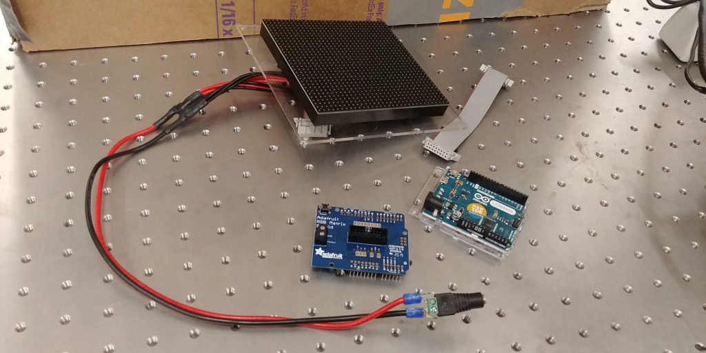
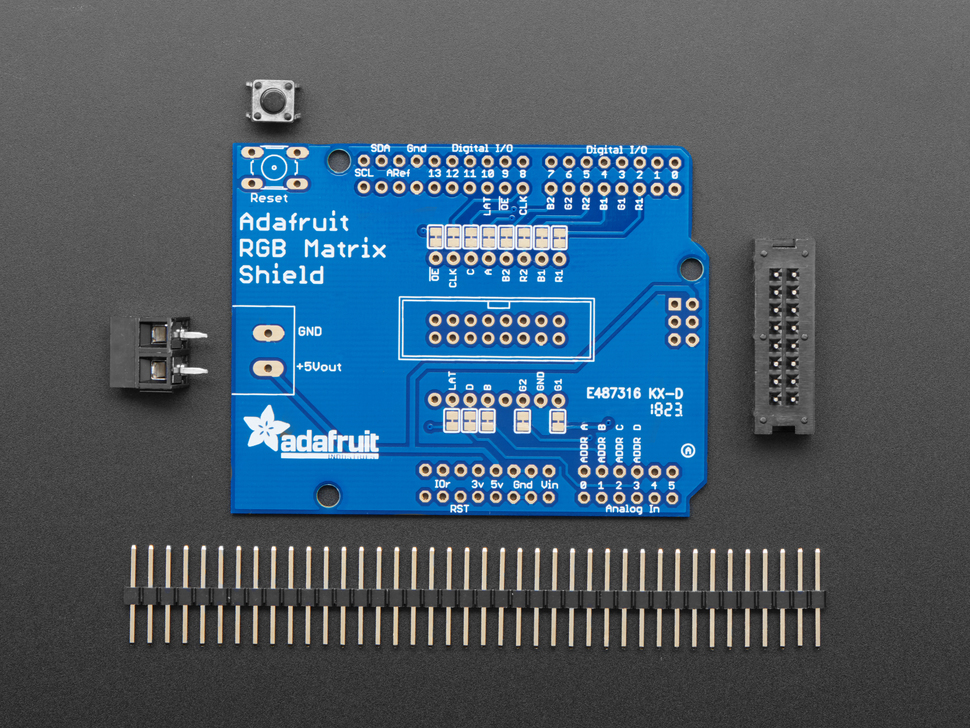
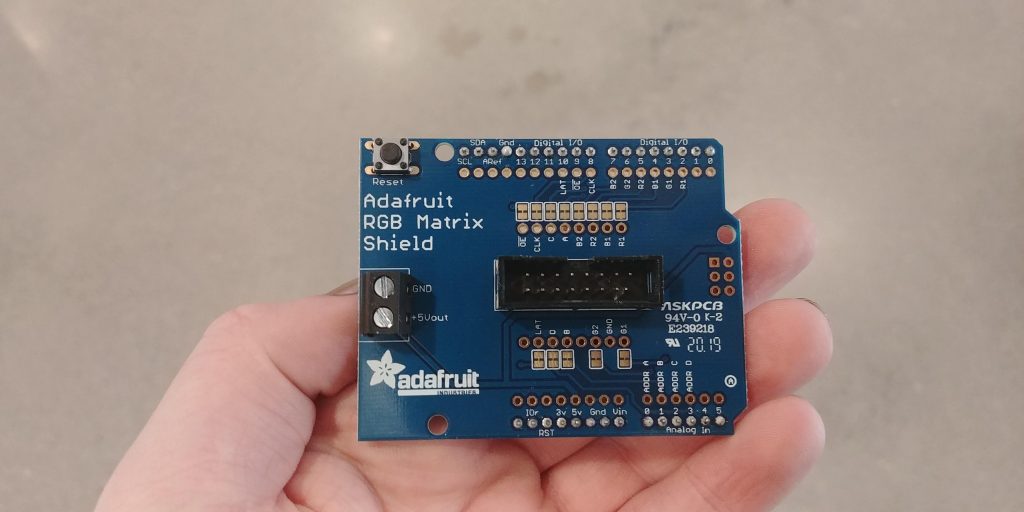
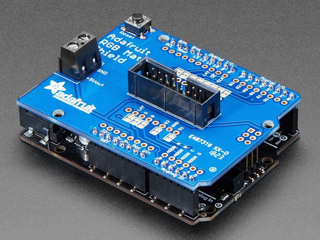
After connecting the Arduino to the LED array — via the RGB Matrix Shield — we tried to run some basic color and shape tests to ensure that everything was running smoothly. Unfortunately, we had an issue where only half of the LED array was illuminated properly.

Pictured, the three components in the LED array

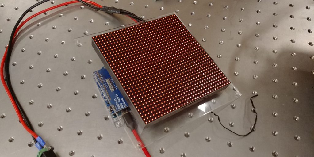
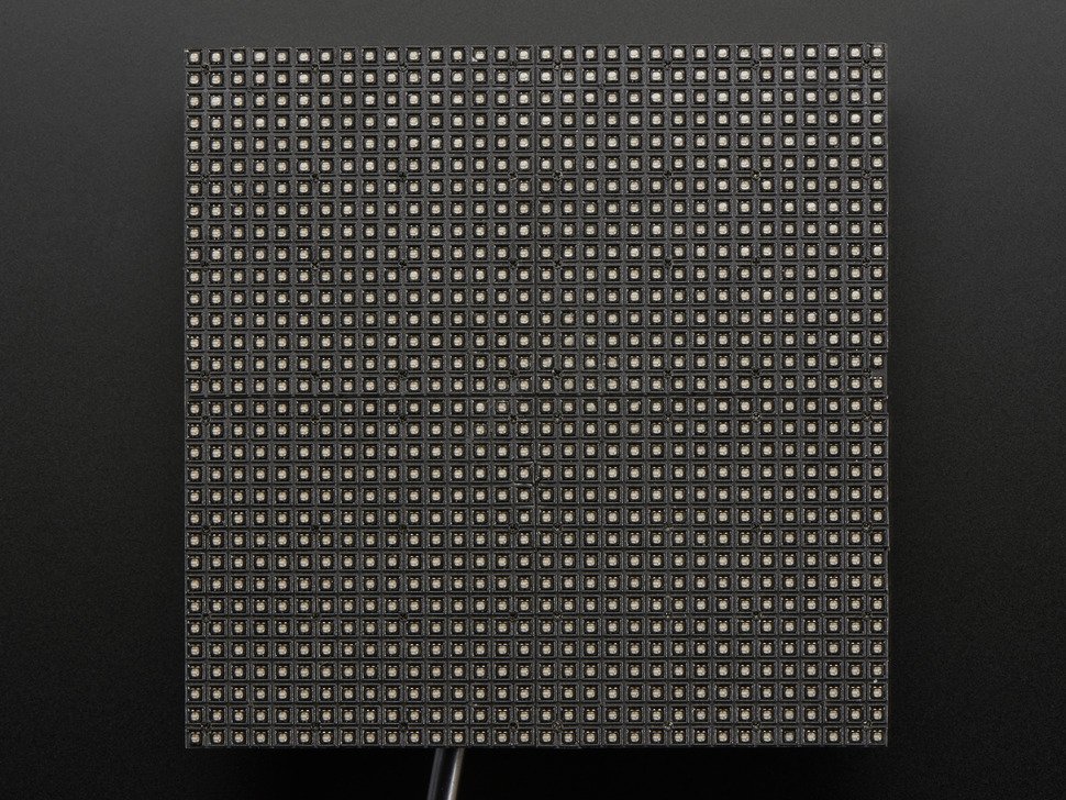
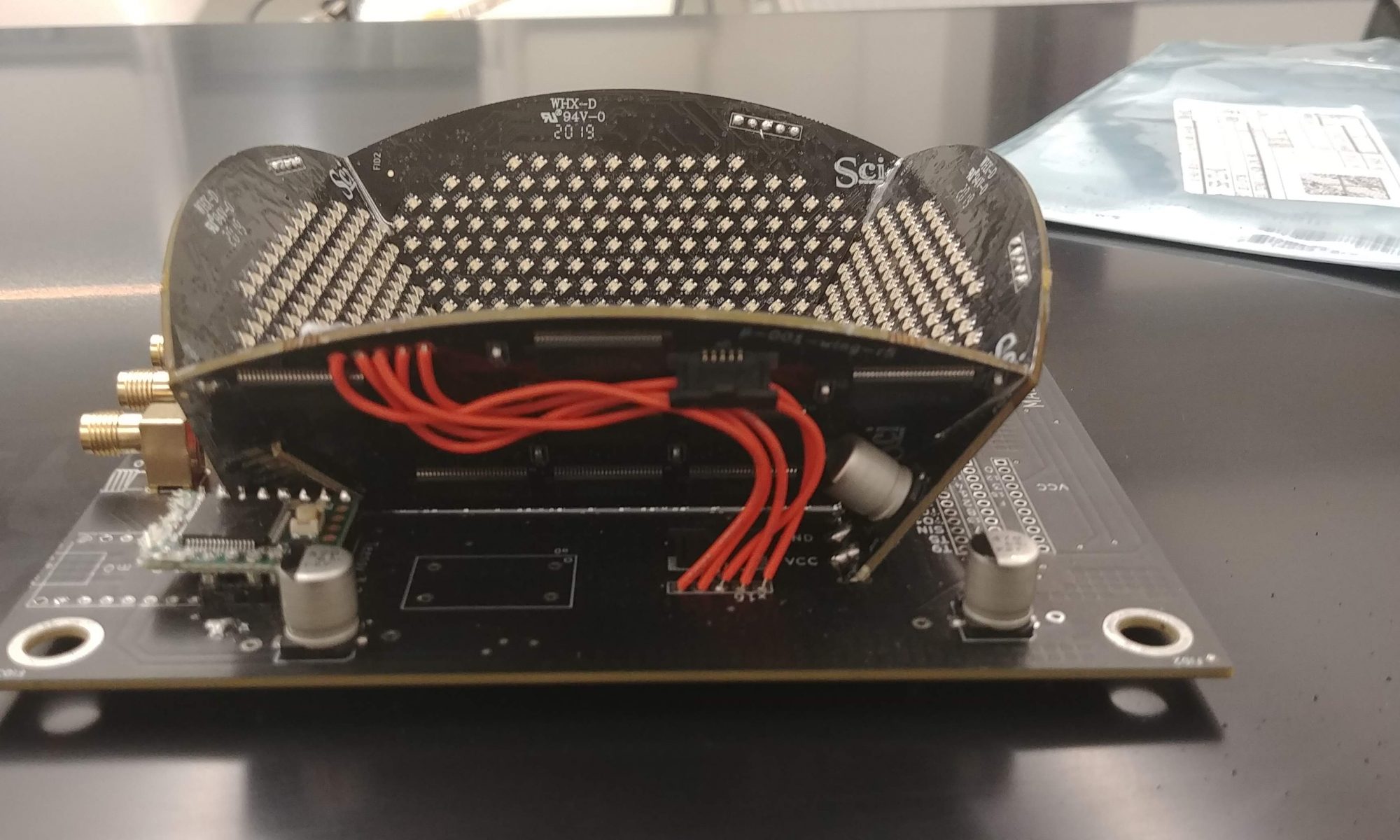
Thus, I began an extensive debugging process. When the 32×32 LED Matrix was receiving power and no data the entire matrix was illuminated (pictured below).

Pictured, the LED array powered but with no data.

As a result, I suspected that the issue was data related. With either the ribbon cable or the LED Matrix at fault. As such, I unmounted the array and swapped out the ribbon cable. This didn’t solve the issue.

Thankfully, we had another 32×32 LED Matrix in the lab so I mounted the other LED Matrix with the new ribbon cable. This, too, didn’t solve the issue.

Just to be safe, I again swapped the new ribbon cable for the previous ribbon cable. Again, no change.

Having ruled out both the ribbon cable and the LED Matrix itself as issues, I circled back and did a quick sanity check to make sure there wasn’t a flaw in the code that I was running. This was the same code that was run in the summer of 2018 so I assumed it was good, but it never hurts to check. I ran some example code straight from the documentation. This too failed to solve the problem.

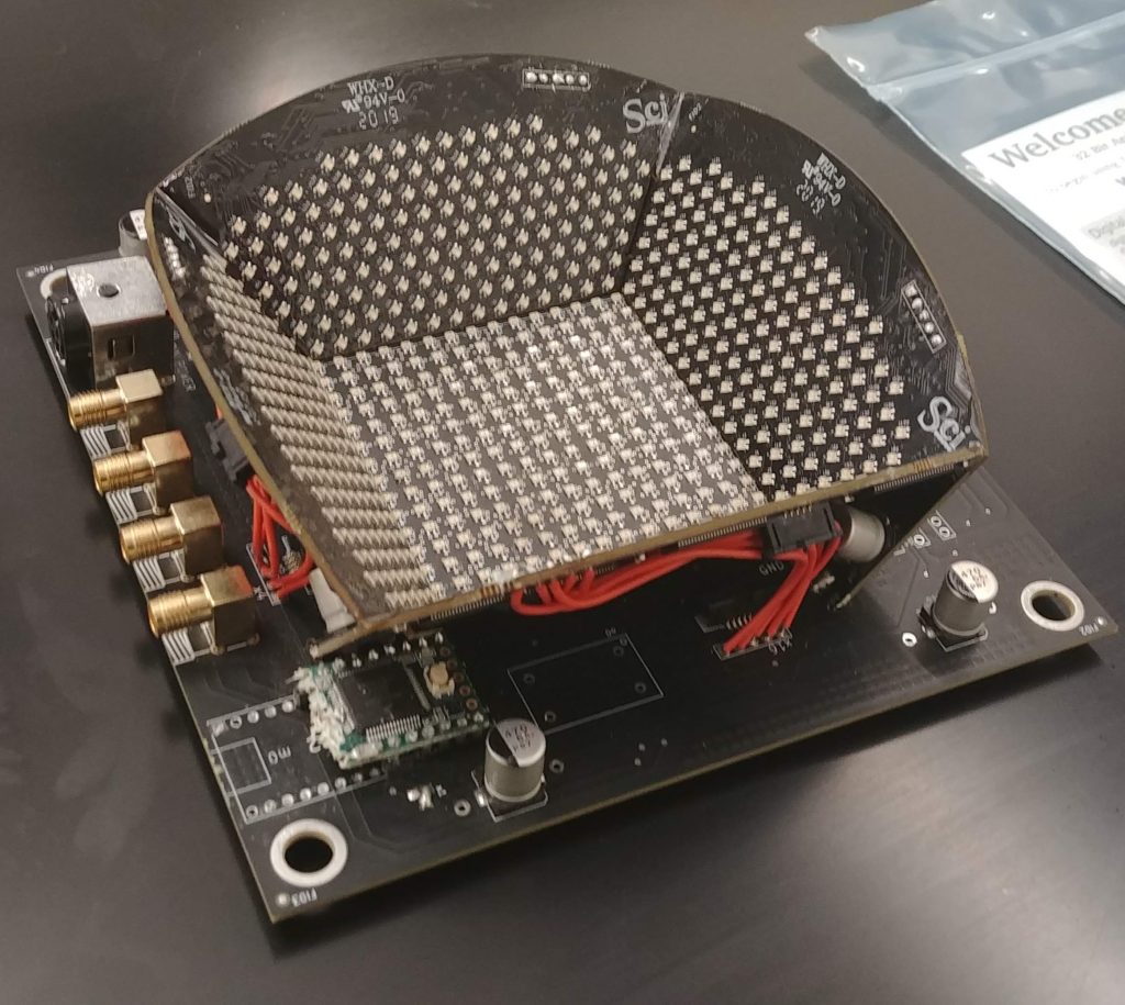
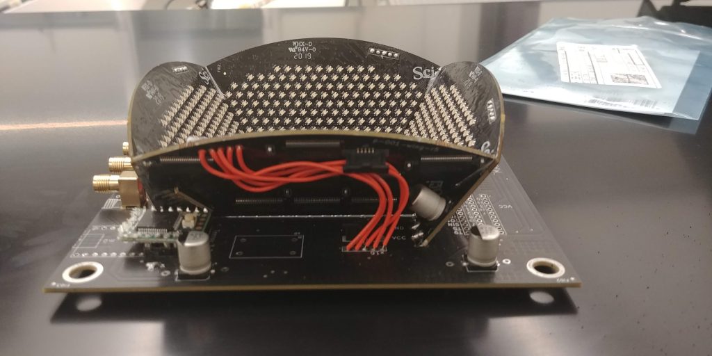
Thinking it may be a power issue, I reseated all the power connections in the entire LED Matrix +Arduino setup and then grabbed the multimeter to check that the correct amount of power is being delivered to the matrix. The multimeter confirmed that there was power delivery to the LED Matrix and to the Arduino. I then checked the power supply to make sure that it was rated to deliver the correct amount of amps and volts (it was). Lastly, I used the multimeter to check if the LED Matrix was actually receiving the 5V and 2A it was supposed to be. Pictured below is part of that process.

Pictured, probing the LED array with a multimeter

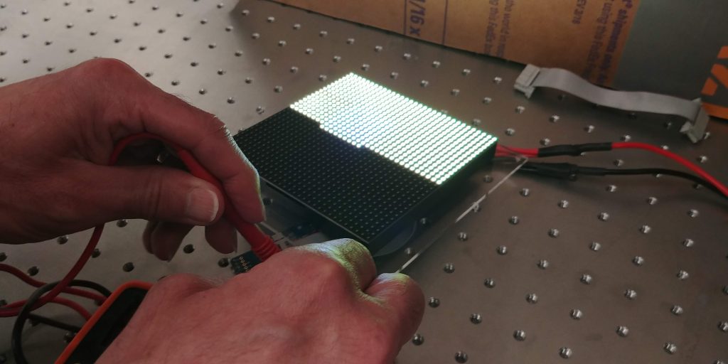
Frustratingly, the multimeter proved that the LED matrix was receiving 5V and 2A.

Thinking it may be a soldering issue, I brought in our resident electronics specialist, Ed, to look at our soldering work. He confirmed that it looked fine. He also went over my power work and came to the same conclusions that I did. 

At this point, both he and I were pretty stumped.  I don’t think it’s an Arduino issue because the Arduino boots fine. It could be an internal issue with the shield and, if so, I’d need to wire the ribbon cable to the Arduino via jumper wires to double-check. Ed thinks it might be a power issue, but I am skeptical since everything on the multimeter makes sense. 

I planned to go back into the lab and follow up on my hunch, but then Swarthmore College switched to online learning due to the COVID-19 pandemic and I was/am unable to get into the lab to debug any further.

Setting Up The RGB Matrix Shield

Note: This post was intended to be published in mid-February 2020, but was delayed by the COVID-19 pandemic.

The RGB Matrix Shield has arrived! Like many products from Adafruit, some assembly is required to get the shield up and running.

Pictured, all of the components included when purchasing the RGB Matrix Shield Shield. Picture from the Adafruit Website

Unfortunately, none of the current Ganapati lab members had soldered in over a year. So, after a quick refresher, we set about soldering together the RGB Matrix Shield. The first step was to solder on the reset switch, the screw terminals, and the male ribbon connector.

Pictured, the components successfully soldered on the RGB Matrix Shield

The silkscreen made it very easy for us to ensure that we didn’t solder on any component backward. For example, the notch on the ribbon connector silk screen lined up with the notch on the ribbon connector part. This may seem trivial, but any design choice to lower the chance of failure is much appreciated.

After soldering on the components, the next thing we did was solder on all the header pins. This proved to be slightly annoying because we wanted to ensure that the header pins were orthogonal to the shield PCB in order to eliminate any problems down the road. This was not as easy as we’d hoped it would be.

After some adjustments to our soldering approach, we managed to get all the header pins oriented in an acceptable fashion and completed the shield assembly. Up next, putting all the pieces together.

Pictured, 32×32 LED Matrix, RG Matrix Shield, and an Arduino Leonardo

Back To Basics, New and Improved

Note: This post was intended to be published in early February 2020, but was delayed by the COVID-19 pandemic.

At the end of the 2019 Fall semester, I got the dome array set up and working for a short while. Unfortunately, over the winter months, the teensy Arduino managed to break on this dome as well. As such, we decided to “go back to basics” and reimplement the original 32×32 LED matrix because it didn’t have nearly as many technical hiccups.

Pictured, a 32×32 LED Matrix. Photo from Adafruit’s Website.

In the old setup we wired the Arduino directly to the ribbon cable that was connected to the LED array via jumper wires and a breadboard, but — as you can see below — this wiring is a quite involved process.

Pictured, Final Amount Of Jumper Cables Connected To A Ribbon Cable In Order To Interface With An Arduino
Pictured, Final Amount Of Jumper Cables Connected To An Arduino In Order To Interface With A Ribbon Cable

With a little bit of poking around, I found out that Adafruit sells an RGB Matrix Shield. In fact, they recommend using this shield to connect from an Arduino to a ribbon cable. With this shield, all you need to do is plug in the ribbon cable. Much simpler and less error-prone than working with ~35 jumper wires.

RGB Matrix Shield. Photo from Adafruit’s Website

As such, the lab has decided to buy one to connect our arduino to the LED matrix. It is currently enroute as I write this post!

A Small Geometry Problem Part 1

In the lab, we have an LED dome that looks like this.

LED Dome Isometric View
LED Dome Side View

The teensy microcontroller that controls the array is faulty so I plan to replace it.

New Teensy Board

However, getting the old board out isn’t as straight forward as it seems because it abuts one side of the LED dome. As such, we can’t desolder and pull the board out easily. After consulting some Professors, it seems that the best way forward is to remove the bord by brute force! Below are the tools I used to excise the board.

Tools For Exciseing The Board Plus A Board Fragment

With some careful maneuvering, I was able to successfully excise the faulty board without harming the components around it. Now we just have to solder in a new one.

The Excised Board Next To The Empty Slot For A New Teensy Board

Adding in the new board has its own set of challenges. Stay tuned for another update.

Proposed New Workflow

With the new Super Resolution Neural Net underway it may be worth looking at a new workflow for the lab because the new neural net is hosted on the Google Colab platform. Below is the diagram for the new workflow that takes advantage of the fact that the new NN is cloud-based.

Fig 1: New Workflow

Workflow Explained

Step 1: Run Data Collection

Step 2: Upload data to google drive

Step 3: Run NN which will pull from data stored on google drive

Step 4: Take the output of the NN and use it to do single image autofocusing over a single region

Step 5: Send that output to the LED array controller to facilitate the autofocusing

Step 6: Run more data collection

Should You Switch To TensorFlow 2.0

TensorFlow 2.0 officially released on September 30th, 2019. If you’re about to start a new ML project like me you may be a bit confused about which version of TensorFlow you should use. After all, Python 3 was released in 2008 and support for Python 2.7 will finally case on January 1st, 2020. Granted, that’s not a perfect comparison but TensorFlow 1.x has been around since 2015 and there are numerous articles, tutorials, and support forums to guide you to success using TensorFlow 1.x.  I’m here to tell you that you should switch to TensorFlow 2.0 for your next machine learning project.

A Few Of The Key Changes In TensorFlow 2.0

In short, TensorFlow 2.0 is more user-friendly and easier to debug than TensorFlow 1.x. This all comes down to the fact that TensorFlow 2.0 has eager execution by default. This means that you no longer have to stitch together the graph by making tf.*! In addition, there are no more globals meaning it is now easier to keep track of your variables and their scopes.  Last, but certainly not least is that TensorFlow 2.0 will support legacy code from TensorFlow 1.x.

With all that out of the way, it’s easy to see that TensorFlow 2.0 is a good choice for your next project. Now on to learning TensorFlow 2.0.

Tutorials And DocumentationExist For TensorFlow 2.0!

freeCodeCamp’s Tutorial

Coursera Course

MNIST W/ Google Collab

Documentation

Sources And More Reading

https://towardsdatascience.com/whats-new-in-tensorflow-2-0-ce75cdd1a4d1

https://www.tensorflow.org/guide/effective_tf2

https://medium.com/tensorflow/effective-tensorflow-2-0-best-practices-and-whats-changed-a0ca48767aff

https://hackernoon.com/everything-you-need-to-know-about-tensorflow-2-0-b0856960c074

Notes On How To Move Things: Ball Screw VS Rack and Pinion

Currently, we’re working on a low-cost plotter to move a specimen slide around on the x-y plane while also having the z-axis to adjust the focus of the optical element. Whew, that’s a lot of moving things. This, of course, begs the question: what is the best way to move things? Currently, we have two options:


Ball Screw:

Cross Section of a Ball Screw on a Screw Shaft

The ball screw would traverse the screw shaft.

From camaster.com “Ball screws are best known for being smooth and friction-free. Over a long axis however, a ball screw-driven system is susceptible to “screw whip”, which is vibration that worsens the faster a screw rotates. This is because of the critical speed of rotation needed over a long axis. To alleviate this, a ball screw driven system requires more gearing or larger motors to compensate for the weight and need to maintain the rapid positioning speeds. This makes the use of a ball screw on an axis over 4’ in length not ideal. That being said, for shorter lengths, this is rarely realized which makes the use of a ball screw a good choice for a short axis on the machine.”

Rack and Pinion:

Image of a Rack and Pinion

For our purposes, it is likely the pinion would be fixed while the rack would move.

Rack-and-pinion drives are far better at handling long axis of motion. Indeed, because of its design, rack and pinion drives can be faster at traversing distances than the ball screw because they can utilize torque more effectively.

They do however have some downsides. From camaster.com,  “Rack-and-pinion’s shortcomings include higher friction and potential backlash if the pinion is not properly engaged.”


Sources:

http://www.cncrouterparts.com/which-is-better-a-screw-or-rack-and-pinion-drive-p-99.html

http://www.camaster.co/faq/whats-better-rack-and-pinion-or-ball-screw/


Notes On Stepper Motors

Different stepper motors are rated at different amounts of steps. For example, we are currently looking at two different stepper motors. One has 32 steps the other has 200 steps. Using the formula 360/(# of steps) we can calculate the step angle.

Step Angle of 32 Step Stepper Motor:  11.25 degrees

Step Angle of 200 Step Stepper Motor: 1.8 degrees


Given the size of the plotter that we are building it seems that buying the 2o step stepper motor is the better choice.

The Trials and Tribulations Of Installing New Lab Computers

So I was able to acquire the new Lab computers without an issue (huge thanks to Jeff–the wonderful sysadmin–for helping me!). I slapped a 1TB SSD in both of them and it was off to the races…almost. Unfortunately,  the very expensive software that we need to use requires Windows. The Lab machines were running Ubuntu, so I contacted ITS to see if they could install Windows on the new Lab machines. After much back and forth, the ultimate answer was yes! Now, with the new Lab machines equipped with Windows, we are finally ready to put them to work.

How To Get New(ish) Lab Computers and Reduce E-Waste!

E-waste is a real issue. A report from the United Nations’ International Telecommunication Union states that 45 million tons of e-waste was generated in 2016.

Like any good Swattie, I am concerned about our environment and want to do what I can to help reduce, reuse, and recycle. However, the fact remains that the Lab needs new computers.

My solution to this predicament is pretty simple. Any institution maintains a set of public use computers. These computers are replaced on a predefined upgrade/replacement cycle which lasts about 3-5 years. If your institution is smart about it,  different sets of computers will be at different stages in this cycle. Meaning, it’s a good bet that your institution is about to throw out some computers.

You should ask for one of those computers.


Here is what I did:

I knew that our CS dept just recently upgraded one of their CS labs. With this knowledge in mind, I went to the sysadmin and asked him if I could have two of the computers he was planning on recycling to use in the Lab I am working in. He said yes. And, just like that, I was able to acquire two new(ish) computers for my Lab.

Now, these computers are on the older side so I have provided some suggestions to speed up and extend the life of your newly acquired computer.


Tips To Extend The Life Of An Older Computer

  • Add more RAM. Older computers usually come with 4 GB of RAM as that was what was deemed a normal amount in the early 2010s. 8 GB should be your minimum.
  • Replace the hard drive with an SSD. This, by far, is the single best thing you can do to speed up an old computer. Even if you don’t want to shell out the money for a large SSD (at the time of writing they are $0.10/GB), replacing the hard drive is a good idea anyway since you don’t know how much use the preexisting hard drive has.
  • If feasible, put on a lightweight operating system like lubuntu.