Note: This post was intended to be published in early March 2020, but was delayed by the COVID-19 pandemic.
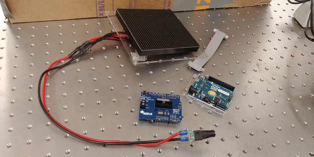
After connecting the Arduino to the LED array — via the RGB Matrix Shield — we tried to run some basic color and shape tests to ensure that everything was running smoothly. Unfortunately, we had an issue where only half of the LED array was illuminated properly.

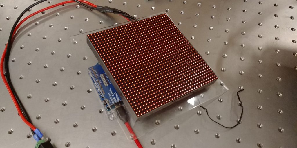
Thus, I began an extensive debugging process. When the 32×32 LED Matrix was receiving power and no data the entire matrix was illuminated (pictured below).

As a result, I suspected that the issue was data related. With either the ribbon cable or the LED Matrix at fault. As such, I unmounted the array and swapped out the ribbon cable. This didn’t solve the issue.
Thankfully, we had another 32×32 LED Matrix in the lab so I mounted the other LED Matrix with the new ribbon cable. This, too, didn’t solve the issue.
Just to be safe, I again swapped the new ribbon cable for the previous ribbon cable. Again, no change.
Having ruled out both the ribbon cable and the LED Matrix itself as issues, I circled back and did a quick sanity check to make sure there wasn’t a flaw in the code that I was running. This was the same code that was run in the summer of 2018 so I assumed it was good, but it never hurts to check. I ran some example code straight from the documentation. This too failed to solve the problem.
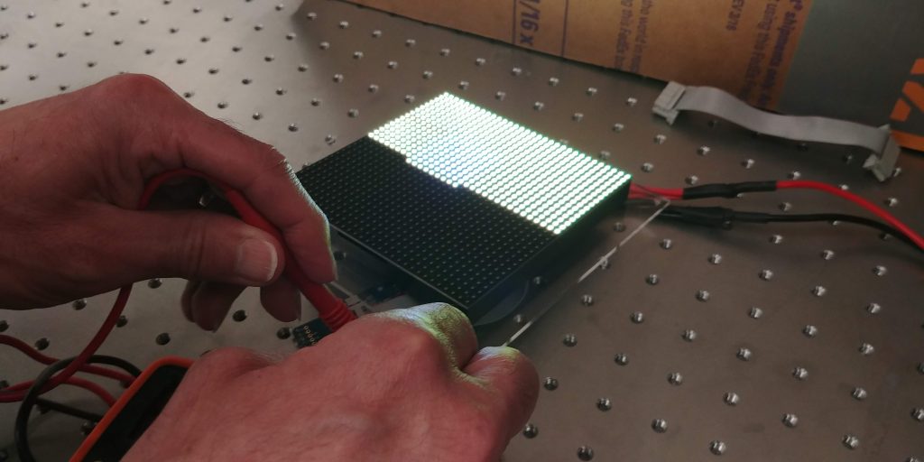
Thinking it may be a power issue, I reseated all the power connections in the entire LED Matrix +Arduino setup and then grabbed the multimeter to check that the correct amount of power is being delivered to the matrix. The multimeter confirmed that there was power delivery to the LED Matrix and to the Arduino. I then checked the power supply to make sure that it was rated to deliver the correct amount of amps and volts (it was). Lastly, I used the multimeter to check if the LED Matrix was actually receiving the 5V and 2A it was supposed to be. Pictured below is part of that process.

Frustratingly, the multimeter proved that the LED matrix was receiving 5V and 2A.
Thinking it may be a soldering issue, I brought in our resident electronics specialist, Ed, to look at our soldering work. He confirmed that it looked fine. He also went over my power work and came to the same conclusions that I did.
At this point, both he and I were pretty stumped. I don’t think it’s an Arduino issue because the Arduino boots fine. It could be an internal issue with the shield and, if so, I’d need to wire the ribbon cable to the Arduino via jumper wires to double-check. Ed thinks it might be a power issue, but I am skeptical since everything on the multimeter makes sense.
I planned to go back into the lab and follow up on my hunch, but then Swarthmore College switched to online learning due to the COVID-19 pandemic and I was/am unable to get into the lab to debug any further.
