Disassembling the Fourier Ptychographic Microscope

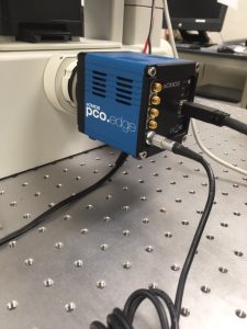
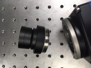
The Arduino and pco camera were unplugged from the power strip and the usb ports of the laptop. The picture below shows the camera attached to the microscope. The black and sliver cables were both removed.

Next, the camera was removed from the C mount of the microscope. The C mount adapter was removed from the camera so that a protective cover could be placed over the lens.

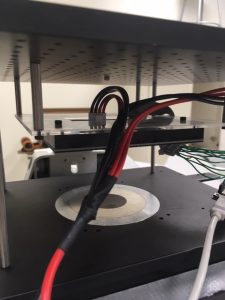
The LED matrix is affixed to an acrylic baseplate that is suspended above the microscope stage. The red and black wires are connected to the power supply, and were unplugged first. The acrylic baseplate was unscrewed from the top of the microscope.

A wiring guide for the 32×32 LED matrix may be found here . The jumper wires were disconnected from the LED array so that the Arduino could be packaged separately.


To reassemble the microscope, the LED array must be rewired and reaffixed to the top of the microscope. The array should be reconnected to the power supply and the Arduino should be reconnected to the USB port of the controlling computer.

The C mount must be reattached to the camera, which should also be reconnected to power and the laptop.


Microscope Stand Prototype I

Our microscope assembly includes an LED array, foldscope lenses, and a cellphone. The first design for our microscope stand used a LEGO base to hold the LED array in place beneath the foldscope and cellphone arrangement, which were supported by a piece of cardboard. The second design, shown below, was made in Autodesk and 3D printed in the college makerspace.

The base of the stand is scaled to snugly hold the LED array in place. The four narrow supports along the sides of the stand are intended to hold the phone, foldscope, and slide assembly in place at four different heights, allowing for very crude z-distance adjustment.

Because the 3D design is uncomplicated, it was decided that future prototypes should be made of laser cut acrylic pieces and fitted together. The 3D printing job was too large to print on a practical timetable, and during early prototyping stages rapid iteration is desirable. The laser cuts take only a few minutes at a time, while the 3D print job took more than 24 hours.

This simple stand design was useful for developing skills in Autodesk and 3D printing, and for holding the microscope setup steady while attempting to take calibration images. However, it does not allow any fineness in z-distance adjustment and no movement at all in the x and y directions. Future designs will include 3 stepper motors arranged so that minute changes can be made in all three directions for best image quality and control.

Determining Magnification of a Microscope Lens

For our project, we need to know the magnifying power of a lens with a fairly high degree of accuracy. Some lenses have unknown or obviously inaccurate magnification information, while others have approximately accurate information that is not precise enough for computations. In either case, it is useful to be able to calculate the magnifying power for ourselves.

A microscope slide like the one above, whose divisions are a known distance apart, is used to perform the calculation.

First, a picture is taken of the ruler slide using the desired magnification. Next, the individual pixels between two divisions are counted. This is done using any editing software with a single-pixel brush size. Finally, the pixel size on the sensor plane of the imaging device must be known. Camera documentation should include this information.

Magnification is found by multiplying the counted number of pixels per division by the pixel size on the sensor plane and dividing by the actual distance of the divisions on the slide. An example calculation is performed below on a lens of approximately 10x magnification:

Calibration slide with 50 um divisions
Camera with 6.5 um pixel size
Counted 72 pixels per division

Magnification = (6.5*72)/50 = 9.36x