Links to useful data collection and processing documentation
Image Collection Procedure
Image Preprocessing and Reconstruction Procedure
Shift-Add Optimized Element Data Processing Procedure
Virtual Environment Setup

Directed Reading for Members of The Ganapati Lab. Currently: Jake Chanenson and Yifan Yan
Links to useful data collection and processing documentation
Image Collection Procedure
Image Preprocessing and Reconstruction Procedure
Shift-Add Optimized Element Data Processing Procedure
Virtual Environment Setup
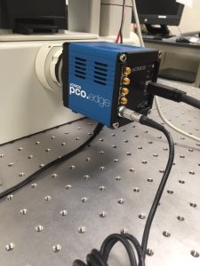
The Arduino and pco camera were unplugged from the power strip and the usb ports of the laptop. The picture below shows the camera attached to the microscope. The black and sliver cables were both removed.
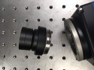
Next, the camera was removed from the C mount of the microscope. The C mount adapter was removed from the camera so that a protective cover could be placed over the lens.
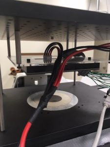
The LED matrix is affixed to an acrylic baseplate that is suspended above the microscope stage. The red and black wires are connected to the power supply, and were unplugged first. The acrylic baseplate was unscrewed from the top of the microscope.
A wiring guide for the 32×32 LED matrix may be found here . The jumper wires were disconnected from the LED array so that the Arduino could be packaged separately.
To reassemble the microscope, the LED array must be rewired and reaffixed to the top of the microscope. The array should be reconnected to the power supply and the Arduino should be reconnected to the USB port of the controlling computer.
The C mount must be reattached to the camera, which should also be reconnected to power and the laptop.
Our microscope assembly includes an LED array, foldscope lenses, and a cellphone. The first design for our microscope stand used a LEGO base to hold the LED array in place beneath the foldscope and cellphone arrangement, which were supported by a piece of cardboard. The second design, shown below, was made in Autodesk and 3D printed in the college makerspace.
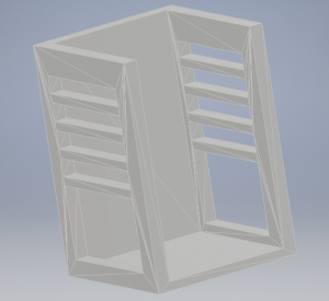
The base of the stand is scaled to snugly hold the LED array in place. The four narrow supports along the sides of the stand are intended to hold the phone, foldscope, and slide assembly in place at four different heights, allowing for very crude z-distance adjustment.
Because the 3D design is uncomplicated, it was decided that future prototypes should be made of laser cut acrylic pieces and fitted together. The 3D printing job was too large to print on a practical timetable, and during early prototyping stages rapid iteration is desirable. The laser cuts take only a few minutes at a time, while the 3D print job took more than 24 hours.
This simple stand design was useful for developing skills in Autodesk and 3D printing, and for holding the microscope setup steady while attempting to take calibration images. However, it does not allow any fineness in z-distance adjustment and no movement at all in the x and y directions. Future designs will include 3 stepper motors arranged so that minute changes can be made in all three directions for best image quality and control.
For our project, we need to know the magnifying power of a lens with a fairly high degree of accuracy. Some lenses have unknown or obviously inaccurate magnification information, while others have approximately accurate information that is not precise enough for computations. In either case, it is useful to be able to calculate the magnifying power for ourselves.

A microscope slide like the one above, whose divisions are a known distance apart, is used to perform the calculation.
First, a picture is taken of the ruler slide using the desired magnification. Next, the individual pixels between two divisions are counted. This is done using any editing software with a single-pixel brush size. Finally, the pixel size on the sensor plane of the imaging device must be known. Camera documentation should include this information.
Magnification is found by multiplying the counted number of pixels per division by the pixel size on the sensor plane and dividing by the actual distance of the divisions on the slide. An example calculation is performed below on a lens of approximately 10x magnification:
Calibration slide with 50 um divisions
Camera with 6.5 um pixel size
Counted 72 pixels per division
Magnification = (6.5*72)/50 = 9.36x
Currently, we’re working on a low-cost plotter to move a specimen slide around on the x-y plane while also having the z-axis to adjust the focus of the optical element. Whew, that’s a lot of moving things. This, of course, begs the question: what is the best way to move things? Currently, we have two options:
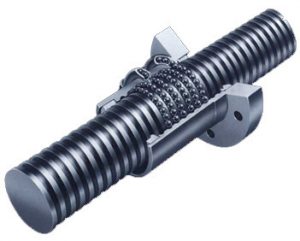
The ball screw would traverse the screw shaft.
From camaster.com “Ball screws are best known for being smooth and friction-free. Over a long axis however, a ball screw-driven system is susceptible to “screw whip”, which is vibration that worsens the faster a screw rotates. This is because of the critical speed of rotation needed over a long axis. To alleviate this, a ball screw driven system requires more gearing or larger motors to compensate for the weight and need to maintain the rapid positioning speeds. This makes the use of a ball screw on an axis over 4’ in length not ideal. That being said, for shorter lengths, this is rarely realized which makes the use of a ball screw a good choice for a short axis on the machine.”
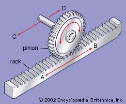
For our purposes, it is likely the pinion would be fixed while the rack would move.
Rack-and-pinion drives are far better at handling long axis of motion. Indeed, because of its design, rack and pinion drives can be faster at traversing distances than the ball screw because they can utilize torque more effectively.
They do however have some downsides. From camaster.com, “Rack-and-pinion’s shortcomings include higher friction and potential backlash if the pinion is not properly engaged.”
http://www.cncrouterparts.com/which-is-better-a-screw-or-rack-and-pinion-drive-p-99.html
http://www.camaster.co/faq/whats-better-rack-and-pinion-or-ball-screw/
Different stepper motors are rated at different amounts of steps. For example, we are currently looking at two different stepper motors. One has 32 steps the other has 200 steps. Using the formula 360/(# of steps) we can calculate the step angle.
Step Angle of 32 Step Stepper Motor: 11.25 degrees
Step Angle of 200 Step Stepper Motor: 1.8 degrees
Given the size of the plotter that we are building it seems that buying the 2o step stepper motor is the better choice.
So I was able to acquire the new Lab computers without an issue (huge thanks to Jeff–the wonderful sysadmin–for helping me!). I slapped a 1TB SSD in both of them and it was off to the races…almost. Unfortunately, the very expensive software that we need to use requires Windows. The Lab machines were running Ubuntu, so I contacted ITS to see if they could install Windows on the new Lab machines. After much back and forth, the ultimate answer was yes! Now, with the new Lab machines equipped with Windows, we are finally ready to put them to work.
E-waste is a real issue. A report from the United Nations’ International Telecommunication Union states that 45 million tons of e-waste was generated in 2016.
Like any good Swattie, I am concerned about our environment and want to do what I can to help reduce, reuse, and recycle. However, the fact remains that the Lab needs new computers.
My solution to this predicament is pretty simple. Any institution maintains a set of public use computers. These computers are replaced on a predefined upgrade/replacement cycle which lasts about 3-5 years. If your institution is smart about it, different sets of computers will be at different stages in this cycle. Meaning, it’s a good bet that your institution is about to throw out some computers.
You should ask for one of those computers.
Here is what I did:
I knew that our CS dept just recently upgraded one of their CS labs. With this knowledge in mind, I went to the sysadmin and asked him if I could have two of the computers he was planning on recycling to use in the Lab I am working in. He said yes. And, just like that, I was able to acquire two new(ish) computers for my Lab.
Now, these computers are on the older side so I have provided some suggestions to speed up and extend the life of your newly acquired computer.
Earlier this week I learned the baffling fact that academics have to pay to get their work published. I decided to do a little digging and this is what I found:
Well, in the 1950s there was no good way to disseminate scientific findings so the British government tried to improve this by incentivizing book publishers to publish scientific articles. These publications turned into journals. At first, publication in these journals did not have a huge bearing on one’s academic career. However, over time, some journals were known for publishing a higher frequency of novel and influential papers. These journals gained prestige. As a result, it was desirable to publish in them. Suddenly, one’s worth as an academic depended on their publications. This resulted in the now familiar mantra of “publish or perish.” Even though publishing was an essential part of academia, some publishers were struggling financially. The larger publishers took this opportunity to acquire smaller publishers — thereby consolidating their power and creating today’s publishing landscape.
Unfortunately, its really hard to get a large enough portion of academia to forgo publishing in prestigious journals because their livelihood is on the line. Thus, the move from these closed off publishers to open access publishing has been a slow process. Moreover, many publishers have co-opted the open access movement to squeeze even more money out of academics. Now, many publishers have the option for academics to publish their work open access, but to do so is considerably more expensive than publishing not open access. Given these factors, it is unclear what will happen next.
This semester, we collected 90 datasets of low resolution flatworm images to train the neural network on. The tomographic output is a high resolution and has a wide field of view. When training on the neural net is complete, we will be capable of single-shot reconstruction. Assuming the training is successful, we will write a paper on this research during the spring semester.
The foldscope project is proceeding more rapidly now that the flatworm project is nearing completion. We have prototyped multiple FPM-compatible assemblies using Legos and other material. Once our design is finalized, instructions for duplication will be posted to the blog along with images of the final product. We have experimented with apache cordova and other tools that will allow us to wirelessly control our LED array in sync with an iPhone camera using a simple app. The ESP8266 dev board will be the key to wireless synchronization. The FPM app and any other software will be made available once complete so that any person with a foldscope, LED array, and cell phone can achieve single-shot Fourier reconstruction.