
The Fourier Ptychographic Microscopy (FPM) so far in Ganapati’s lab has been performed with a flat 32×32 LED array. With a flat array, you can light up one LED at a time to acquire different illumination angles for imaging. However, there are many disadvantages to the current flat LED array set-up. For example, one major issue regarding the flat LED array is that it is programmed by Arduino, which does not contain memory. When we tried to reprogram the array to light up random multiplexed patterns of LEDs rather than one LED at a time (a change that could greatly reduce data acquisition time), we were unable to do so because the Arduino could not store information on the location of the LED coordinates. In addition, the flat LED is not very bright and contains smaller illumination angles, producing low resolution images that contain less intensity information and therefore decreases the space-bandwidth product (SBP) of the FPM reconstructed images.
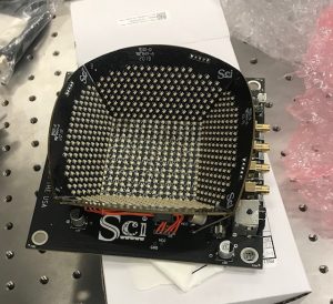
By replacing the flat LED array with an LED dome purchased from Spectral Coded Illumination (Sci), many improvements could be made to our current FPM procedure. We can easily program the dome to produce random multiplexed patterns of LEDs because the LED can be programmed directly through Python, a much more robust and easy-to-use software than Arduino that can easily store information. In addition, each LED is assigned a specific number rather than a x-y coordinate position, making it easier to write programs that access certain LEDs.
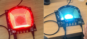
Because of the sloped sides of the array, which produces a dome shape, the LED dome can produce much higher angles for dark field illumination, allowing for increased intensity information of images and thus increasing the SBP of the reconstructed high resolution image. In addition, the LED dome is much brighter than the flat LED array, also contributing to higher quality images and better data for reconstruction. Finally, the dome is programmed to sweep through and illuminate LEDs at a much faster rate than the flat array, significantly reducing data acquisition time.
Once we received the LED dome, we proceeded to download the necessary programs and become familiarized with the various commands for the dome. For instance, the command ‘bf’ illuminates only the brightfield LEDs, which are the LEDs located at low illumination angles and located directly above in sample in the flat roof of the dome. Other examples of commands are shown but not limited to the list below:
‘df’ illuminates only the dark field LEDs.
‘ff’ illuminates all LEDs in the array
‘sb.[r].[g].[b]’ sets the brightness of the array
‘scf’ lights up each LED in the array individually. Takes less than 1 minute to fully scan.
‘x’ clears the array
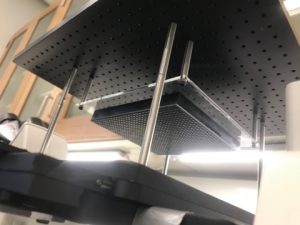
In the next few days we plan to learn more about setting up the hardware trigger modes for direct communication between the PCO camera and dome. We also plan to design and create a way to mount the LED dome onto the microscope so that we can allow for an automated stage. Currently with our flat LED array, we have the array attached to the stage, confining the lab group to manually moving the slides with our hands rather than having a more precise automated stage system.